Category:Regulated Power Supply
Address:No. 121, Huancheng Road, Picheng Town, Danyang City, Jiangsu Province, China
Tel:400-1668-021
Email:kinbo@kinbopower.com
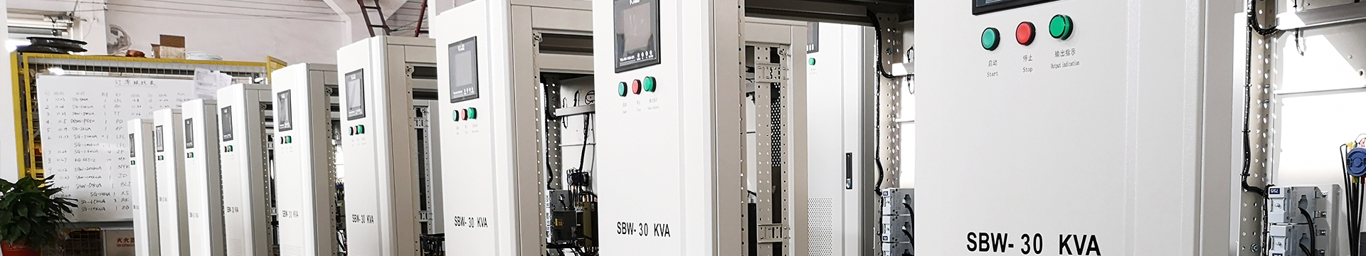
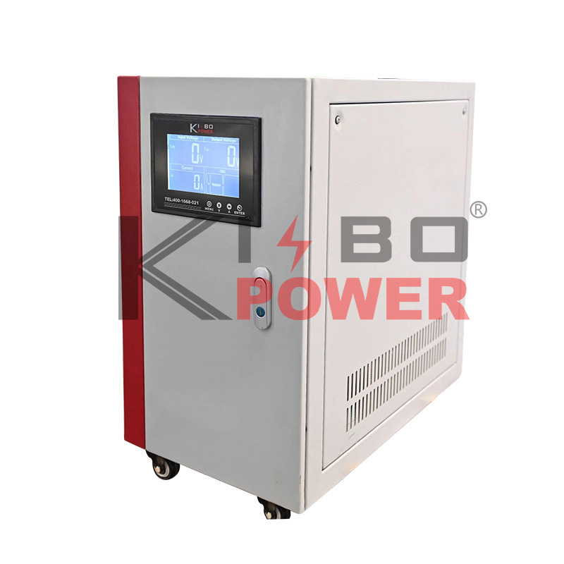
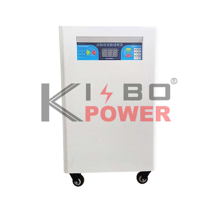
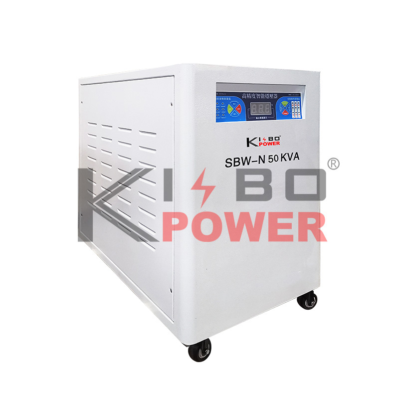
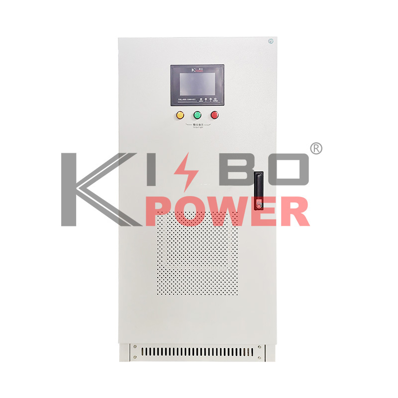
Intro:S(D)BW-N column regulator is composed of single-phase voltage regulating transformer TYQ, voltage detection unit, servo motor control and transmission mechanism, contactor (or circuit breaker) operation circuit, protection circuit, etc. Its electrical schematic is shown in the figure.
S(D)BW-N column regulator is composed of single-phase voltage regulating transformer TYQ, voltage detection unit, servo motor control and transmission mechanism, contactor (or circuit breaker) operation circuit, protection circuit, etc. Its electrical schematic is shown in the figure.
The primary input of the voltage regulating transformer TYQ is a sliding adjustable contact brush, which is flexibly calculated and adjusted on the sliding coil through the sampling circuit, and the secondary output voltage is always controlled within the rated output range, so as to achieve the purpose of automatic voltage regulation. The working principle of its voltage regulation is shown in the figure.
The voltage regulation process is: according to the change of output voltage, the voltage detection unit samples, detects and outputs the signal to control the rotation of the servo motor M, drives the brush set on the voltage regulating transformer TYQ to slide (or roll), and adjusts the primary voltage of the voltage regulating transformer to follow the fluctuation of mains, so as to realize the automatic stabilization of the output voltage within the range allowed by the voltage regulation accuracy, so as to achieve the purpose of automatic voltage regulation.

Technical Parameters
Rated Capacity: 10-100KVA Input Voltage: 380(220)V±15% Output Voltage: 380(220)V±5%
Efficiency: ≥97% Insulation Resistance: ≥10MΩ Waveform distortion: ≤0.1%
Operating Frequency: 50Hz to 60Hz Voltage Regulation Accuracy: ±(1〜5)%

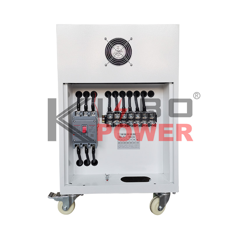
(a) After selecting the manual automatic voltage regulation (the automatic position has been set at the factory) through the button in the above picture, close the input air switch QF2 (INPUT Breaker), and then the voltage regulator is connected to the power supply to complete the input power supply power-on test.
(b) The meter on the front panel can check the input voltage, output voltage, and output current.
(c) The switch after closing the voltage regulator and the output air switch QF3 (OUTPUT Breaker) are closed, and the voltage regulator supplies power to the bus normally.
(d) Manual mode can be selected; When the manual voltage regulation method is selected, the manual boost or buck button on the jogging control board can adjust the required output voltage.
 KBSBW Digital Display Compensated AC Voltage Regulator
 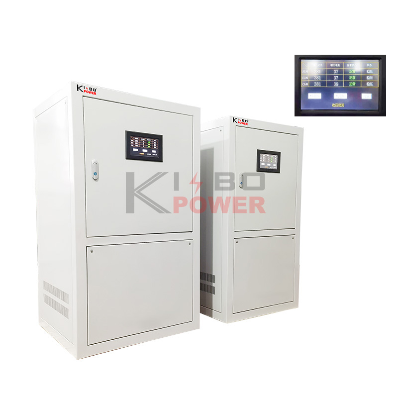 KBZ Smart Contactless
 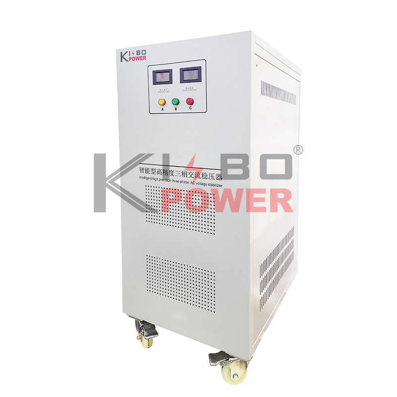 SBW-H High-Precision AC Voltage Regulator
 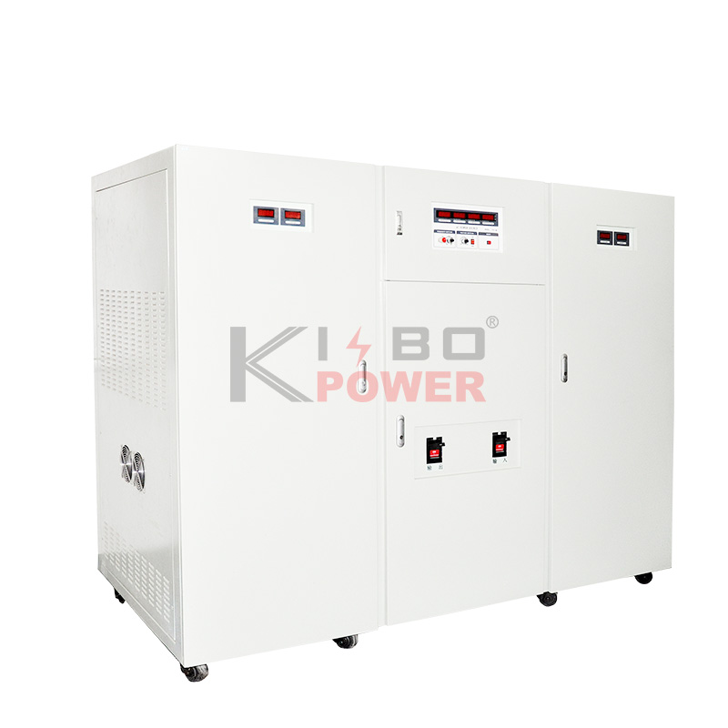 Variable Frequency Regulated Power Supply
 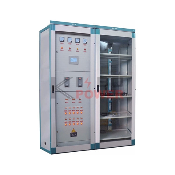 KBGZDW Series DC Power Supply Panel
 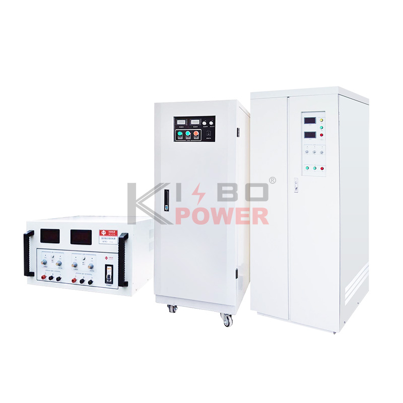 DC regulated power supply
 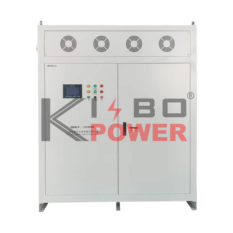 SBW-F Series Three-Phase Adjustable High-Power Voltage Regulator SBW-N New Column-Type Voltage Regulator