
Category:Filter Reactor
Address:No. 121, Huancheng Road, Picheng Town, Danyang City, Jiangsu Province, China
Tel:400-1668-021
Email:kinbo@kinbopower.com
Intro:Kinbo Technology's active power filter is an innovative device for power harmonics management, developed using modern power electronics technology and digital signal processing technology based on high-speed DSP devices. It consists of two main parts: the reference current computation circuit and the compensation current generation circuit.
Product Details:
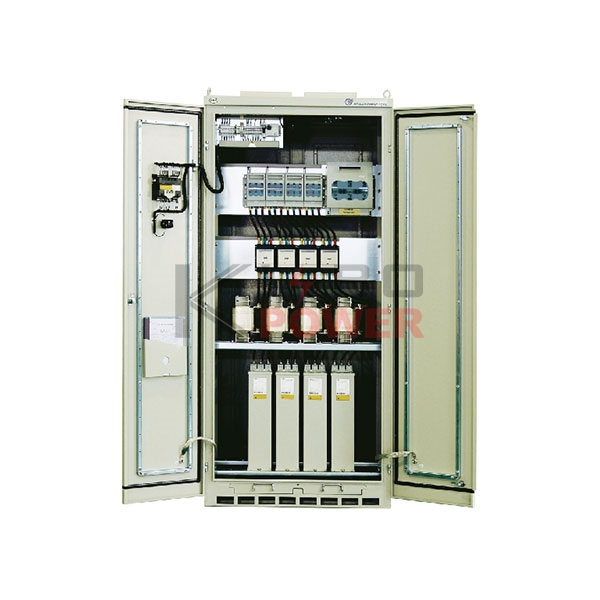
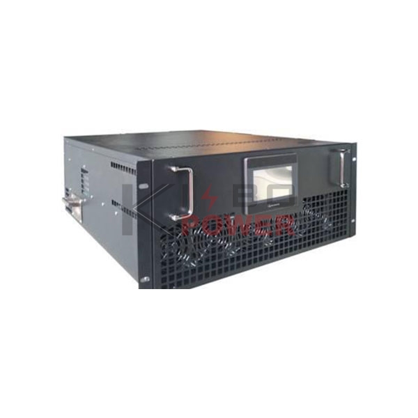
Product Description
Kinbo Technology's active power filter is an innovative device for power harmonics management, developed using modern power electronics technology and digital signal processing technology based on high-speed DSP devices. It consists of two main parts: the reference current computation circuit and the compensation current generation circuit. The reference current computation circuit continuously monitors the current in the line, converts the analog current signals into digital signals, and sends them to the high-speed digital signal processor (DSP) for processing. It separates harmonics from the fundamental wave and sends drive pulses to the compensation current generation circuit in the form of pulse-width modulation (PWM) signals, driving IGBT or IPM power modules to produce compensation currents that are equal in amplitude but opposite in phase to the harmonic currents in the power grid, thereby compensating or canceling the harmonic currents and actively eliminating power harmonics.
Technical Specifications
| Wiring Method | Three-phase Three-wire / Three-phase Four-wire | ||
| Input Voltage | 3×380V±10% | ||
| Input Frequency | 50Hz±2% | ||
| Response Time | ≤20ms | ||
| Switching Frequency | 10kHz | ||
| Function Settings | Harmonic compensation only, Reactive power compensation only, Both harmonic and reactive power compensation | ||
| Harmonic Compensation Orders | 2-51st | ||
| Protection Types | DC overvoltage protection, IGBT overcurrent protection, Device temperature protection | ||
| Overload Protection | Automatically limit current to set value, no overload occurs | ||
| Cooling Method | Forced air cooling | ||
| Noise | <65dB | ||
| Operating Temperature Range | -10°C ~ +45°C | ||
| Operating Humidity | <85%RH non-condensing | ||
| Installation Location | Indoor installation | ||
| Altitude | ≤1000m (de-rate for higher altitudes) | ||
| Wire Entry/Exit Method | According to customer requirements | ||
| Protection Class | IP20 | ||
| Smart Communication Interface | External module | ||
| Remote Monitoring | Optional | ||
| Installation Method | Cabinets | Wall-mounted | Drawer type |
| External Dimensions (mm) (Width × Height × Depth) | 50, 75, 100, 150, 200, 250, 300 800×1000×2200 (Other sizes customizable) | 30, 50, 75 485×275×610 | 30, 50, 75 485×610×275 |
| Color | RAL7035 (Computer gray) | ||
Main Features:
1. Harmonic compensation range: 2-51 times, capable of full compensation for harmonic currents from 2nd to 51st order, or compensation for specific harmonics only;
2. Total harmonic compensation rate: ≥90%
3. The active power filter adopts a modular design, supporting parallel expansion. The parallel capacity is unlimited. If one unit stops due to a fault, the other active filters can continue to operate and perform filtering;
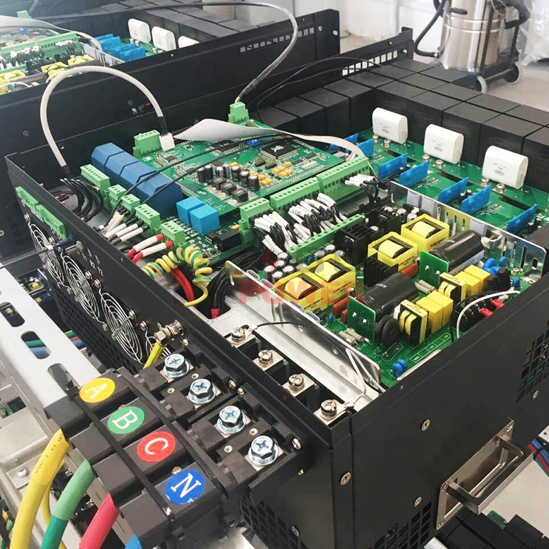
4. The active power filter uses a fully digital, modular control method with DSP + FPGA full digital control and high-power IGBT drive control;
5. The active power filter requires the use of well-known branded and technically mature IGBT devices, ensuring stable performance and reliable quality, with brand-related certification provided;
6. Control algorithm: supports both Fast Fourier Transform (FFT) and instantaneous reactive power algorithms. Closed-loop resonance control algorithm provides strong targeting and high control accuracy;
7. The active power filter supports harmonic compensation, reactive power compensation, and three-phase unbalance compensation simultaneously;
8. The active filter should be independent of grid impedance and system impedance, unaffected by changes in electrical network or system impedance;
9. The filter must avoid overcompensation while filtering, meaning the active filter can filter without generating reactive power, completely avoiding overcompensation. It can also use the remaining energy for reactive power compensation by setting a target power factor;
10. When the system load harmonic exceeds the filter's compensation capacity, the filter should still output rated current according to its capacity, continue effective filtering, and avoid overload or device damage causing shutdown;
11. The active power filter has a maintenance-free feature, ensuring long-term stable operation, and the control unit program possesses self-check functionality;
12. The high-frequency carrier of the active filter itself must not feed back to the grid and should not interfere with other systems and equipment;
13. The active power filter features a user-friendly human-machine interface, allowing parameter control and information reading via a touchscreen LCD panel. The panel can display machine model, total current of each phase load, waveforms, total output current, grid line voltage and waveform, power, total harmonic distortion, spectrum, operating status, fault information, and controls for start, compensation, standby, stop, and self-check reset;
14. The active power filter has stability protection, allowing automatic disconnection from the system if instability occurs;
15. The active power filter has fast and comprehensive fault self-check capabilities and performs corresponding automatic actions;
16. Complete protection functions, including grid over/undervoltage, phase loss, IGBT anomaly, frequency anomaly, device overcurrent, device overtemperature, DC bus over/undervoltage, automatic current limiting during overload, ensuring safe and fault-free operation;
17. The active filter can provide communication interfaces to meet integration requirements with power monitoring systems in certain projects;
18. CT accuracy level 0.5, secondary circuits use RXVVP cables, conductor cross-section not less than 2.5mm²;
19. Utilizing "fiber optic ring network" technology for good synchronization, fast response, and high compensation rate;
20. Employing "proportional-resonant control" technology to avoid grid resonance, ensuring the safety and reliability of the grid;