

 English
 русский
 عربى
 Indonesia
75 kVA is a capacity rating, and it settles one question immediately: how much apparent power the transformer can carry continuously. That is 75,000 VA, which works out to roughly 208 A per phase at 208 V three-phase, 114 A at 380 V, or 90 A at 480 V, and about 60 kW of real power at a 0.8 power factor. Everything after that number — copper or aluminium windings, an 80 K or 115 K temperature rise, dry-type or liquid-immersed construction — decides whether the unit delivers that figure quietly for twenty years or runs hot in its first summer.
What the 75 kVA Rating Actually Covers
The rating is apparent power measured at a stated temperature rise, not a guarantee of watts at the terminals.
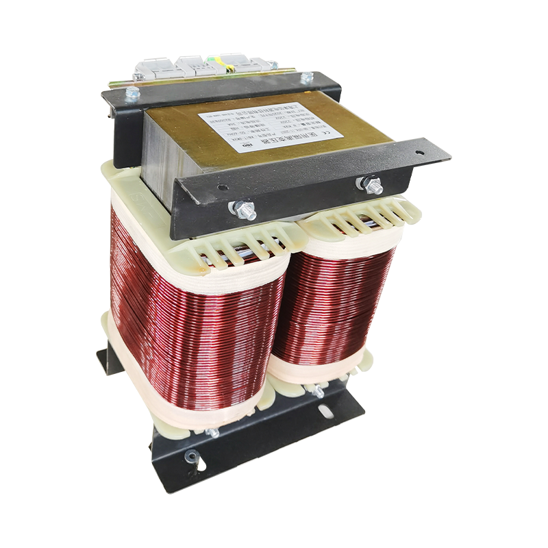
Transformers are rated in kVA because the winding must carry both the current that does useful work and the current that only magnetises and heats. A load drawing 60 kW at unity power factor and a load drawing 60 kW at 0.8 power factor both need 75 kVA of capacity in the second case — 75 kVA × 0.8 = 60 kW — while the first only needs 60 kVA. This is why nameplate kVA, not kW, sets the size of the copper, the core and the cooling surface.
Two details on the nameplate matter as much as the number itself:
- Temperature rise and ambient. A 75 kVA unit rated for 80 K rise at 40 °C ambient is built with more cooling margin than a 115 K version of the same frame. The higher-rise unit is smaller and cheaper, but it runs closer to its insulation limit.
- Harmonic content. Non-linear loads such as rectifiers, drives and IT equipment push current through the winding without adding proportionate real power. A 75 kVA transformer feeding mostly electronic load is often derated to 60–70 kVA of usable capacity unless a K-rated or shielded design is specified.
75 kVA in Amps: The Reference Table Buyers Ask For First
Full-load current depends entirely on system voltage, so the same 75 kVA unit behaves very differently on a 208 V and a 480 V network.
| System | Voltage | Full-load current | Approx. real power at 0.8 PF |
|---|---|---|---|
| Three-phase | 208 V | 208 A | 60 kW |
| Three-phase | 240 V | 180 A | 60 kW |
| Three-phase | 380 V | 114 A | 60 kW |
| Three-phase | 400 V | 108 A | 60 kW |
| Three-phase | 480 V | 90 A | 60 kW |
| Single-phase | 240 V | 312 A | 60 kW |
| Single-phase | 480 V | 156 A | 60 kW |
Use the table for cable and protection sizing, then check it against the actual load schedule. A 75 kVA transformer on a 208 V system carries more than twice the current of the same rating on 480 V, and the primary protection, lug size and enclosure ventilation all follow that difference.
Where a 75 kVA Transformer Is Usually Specified
This rating sits in the middle of low-voltage distribution: large enough to feed a complete workshop panel, small enough to sit in a plant room or a corridor cabinet.
Typical applications include:
- Small and medium workshops where a single 75 kVA step-down unit feeds the machine panel from a 400 V or 480 V service.
- CNC and machine tool clusters, often with a dedicated isolation transformer to limit fault current and separate control circuits from the main supply.
- Commercial buildings using a 75 kVA unit for lighting, HVAC or a tenant distribution board.
- UPS and variable-frequency drive systems, where a matching transformer handles voltage adaptation and harmonic currents on the inverter output.
- Pumping stations, irrigation and grain drying, where rural distribution voltage is unstable and a step-up or step-down unit is required.
- Medical and laboratory rooms, where isolation and clean earth arrangements are mandatory rather than optional.
For UPS and drive duty, the transformer is not a passive accessory. Inverter output contains switching harmonics and DC components, so the unit needs a suitable K-factor, low loss design and adequate thermal margin.
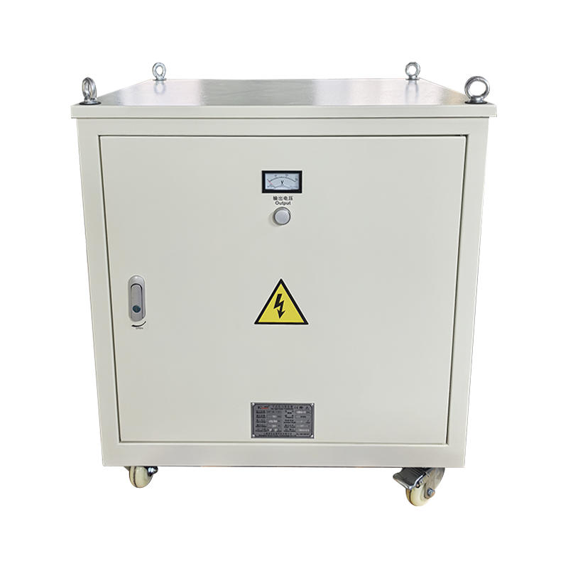
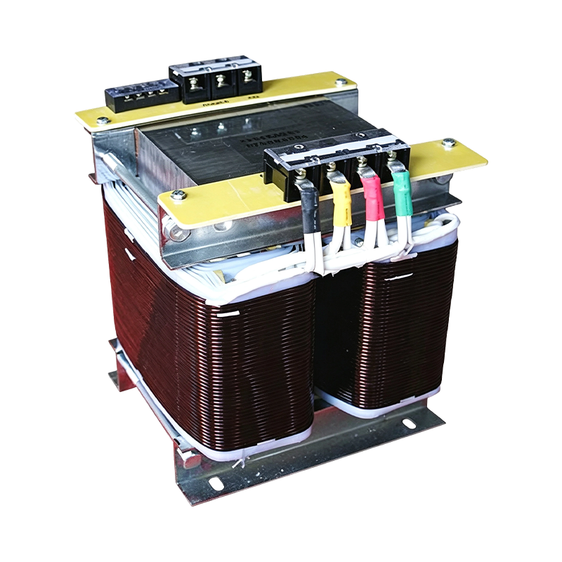
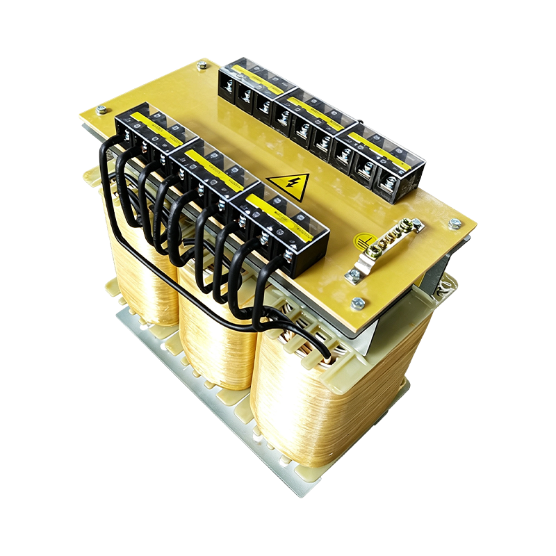 UPS/EPS Variable Frequency Power TransformersDesigned for UPS inverter outputs, EPS emergency loads and VFD front ends, with isolation, neutral establishment and voltage matching in open or enclosed formats.View Product →
Three-Phase or Single-Phase, Dry-Type or Liquid-Filled
A three-phase dry-type unit is the default for indoor industrial work; single-phase and liquid-immersed versions are project-specific choices driven by load shape, location and local code.
| Configuration | Typical fit | Watch point |
|---|---|---|
| Three-phase dry-type | Indoor plant rooms, machine panels, commercial distribution | Needs ventilation; heat stays in the room |
| Single-phase dry-type | Rural distribution, small remote loads, lighting circuits | Higher current per terminal for the same kVA |
| Liquid-immersed | Outdoor pad or pole mounting, harsh environments | Oil containment, fire separation and maintenance access |
| Isolation type with shield | Medical rooms, laboratories, sensitive electronics | Shield bonding and earth arrangement must be designed, not assumed |
Isolation versions deserve their own reading, because the benefit comes from how the winding and shield are earthed rather than from the transformer ratio.
For a deeper explanation of winding arrangement and earthing practice, the site's isolation transformer guide is a useful companion to this overview.
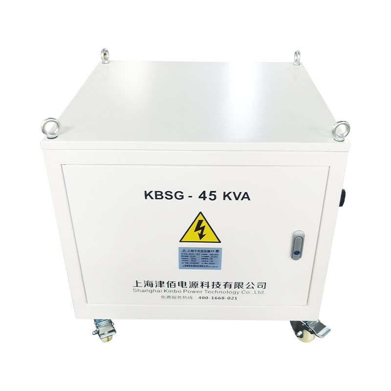
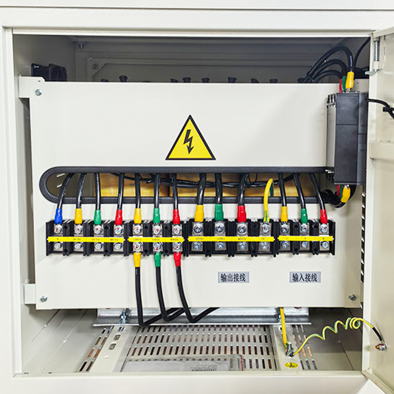 KBSG Isolation Transformers for Distribution SystemsFully isolates input and output, establishes a new neutral ground and converts delta to wye for clean power in distribution, industrial and infrastructure systems.View Product →
Why a 75 kVA Transformer May Still Disappoint
A transformer changes voltage by a fixed ratio, so it cannot hold the output steady while the input swings by 10 or 15 percent.
Where the incoming supply is weak — long rural feeders, shared welding load, generator-backed sites — the secondary voltage follows the primary almost one for one. Equipment then runs at reduced torque, contactors chatter and drives trip on undervoltage. In that situation the correct answer is usually a voltage stabiliser or a combined regulator upstream of the transformer, not a larger transformer.
Sizing also goes wrong in the opposite direction. Engineers sometimes add a transformer to fix low voltage at the far end of a long cable, when the real cause is voltage drop across the cable itself. Measuring the voltage at both ends under load takes twenty minutes and prevents an entire wrong purchase.
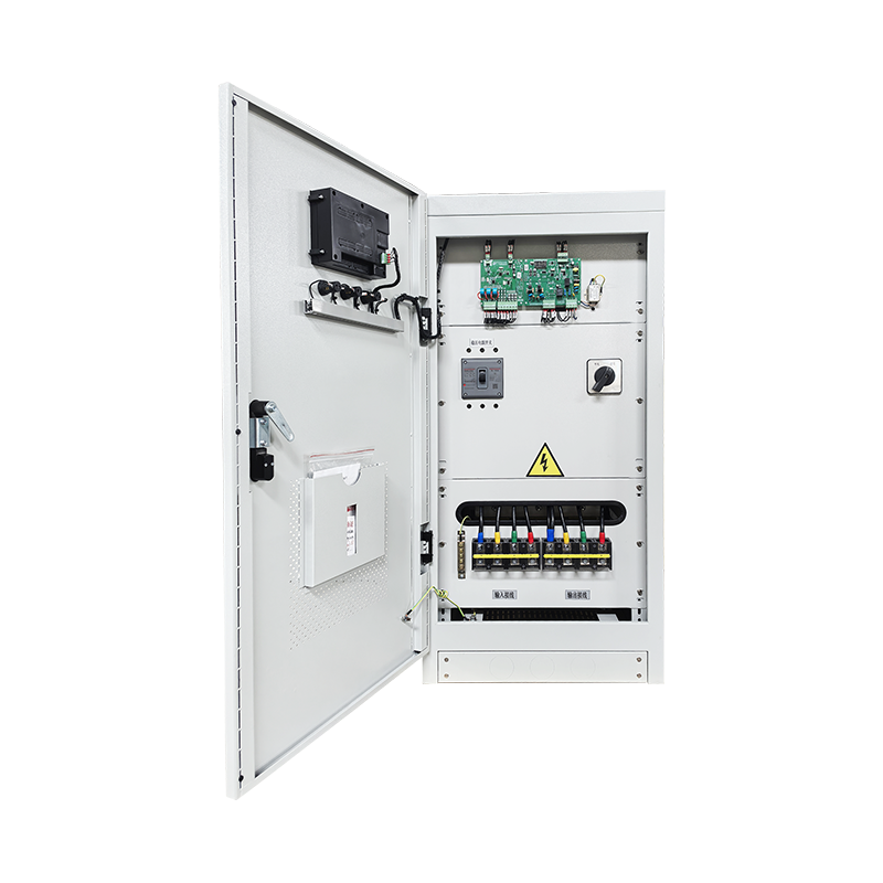 SBW/DBW Automatic Compensated AC Voltage RegulatorsMaintains stable output under supply or load changes for industrial voltage stabilization, with manual/automatic operation and protection; size continuous load at 70–80% of nameplate.View Product →
Sizing a 75 kVA Unit: Load, Starting Current and Growth
Design continuous load at 70 to 80 percent of nameplate, then confirm the short-term demands separately.
- Build the load schedule in kW and kVA. Sum connected loads, apply diversity factors, and note the power factor of each group. Motors and drives dominate the reactive component.
- Check starting current. A 30 kW motor started direct-on-line can pull five to seven times its running current for several seconds. A 75 kVA transformer with a 4 percent impedance will show a noticeable dip on the secondary during that start.
- Leave room for harmonics. If more than 30 percent of the load is electronic, plan on a K-factor design or accept a lower usable rating.
- Allow for ambient and altitude. Above 40 °C or 1,000 m, derating applies and the effective capacity of a 75 kVA unit drops.
- Reserve capacity for growth. A unit sized at 95 percent of present load has no room for the next machine; most plants end up replacing it within two years.
What Drives the Price at This Rating
Winding material and temperature class move the price more than the kVA figure itself does.
- Copper versus aluminium. Copper windings cost more up front but give lower losses and a smaller frame for the same rating; aluminium suits cost-sensitive projects with stable load.
- Temperature rise and insulation class. An 80 K rise design uses more material than a 115 K unit, and a Class H system costs more than Class F.
- Enclosure. A basic IP20 indoor case and an IP54 outdoor enclosure are very different purchases even with identical windings inside.
- Taps and impedance. Off-load taps of ±2 × 2.5 percent are common; unusual tap ranges or non-standard impedance add engineering time.
- Documentation and testing. Routine factory tests, type test reports and third-party certification add cost, and they are usually what a consultant asks for before approval.
The wider power transformer range shows how these options combine in practice, from control and machine tool units to larger distribution designs.
A Short Procurement Checklist
Five checks catch most of the problems that appear after delivery.
- Confirm primary and secondary voltage, vector group and frequency on the datasheet, not just in the quotation text.
- State the ambient temperature and required temperature rise explicitly.
- Ask for the short-circuit impedance and verify it against your protection coordination study.
- Confirm efficiency against the applicable local regulation before comparing prices.
- Require routine test records — ratio, resistance, insulation and applied voltage — with the shipment.
Frequently Asked Questions
How many amps does a 75 kVA transformer supply?
At 400 V three-phase the full-load line current is about 108 A; at 480 V it is about 90 A; at 208 V it rises to about 208 A. Use 75,000 ÷ (√3 × V) for three-phase and 75,000 ÷ V for single-phase.
Can a 75 kVA transformer carry a 60 kW load?
Yes, if the load power factor is 0.8 or better and the unit is not derated for harmonics or high ambient. At unity power factor the same 75 kVA could theoretically supply 75 kW, but continuous loading is normally held near 80 percent of nameplate.
Is 75 kVA the same as 75 kW?
No. kVA measures apparent power — the total current the winding must carry — while kW measures the real power that performs work. The gap between them is the power factor.
Do I need an isolation transformer or a stabiliser?
Choose isolation when the problem is fault current, noise, earth reference or medical safety. Choose stabilisation when the problem is a supply voltage that drifts or sags. Some sites need both, with the regulator placed upstream of the transformer.
A 75 kVA transformer is a well-understood, widely used size, and that is exactly why specification details get copied from project to project without checking. The rating only tells you the apparent power ceiling. Voltage, temperature rise, impedance, harmonic duty and the actual behaviour of the incoming supply decide whether the installation runs smoothly — and those five items are worth confirming in writing before the order is placed.